

Home > CaseGroup NewsIndustry NewsNewsVideo > ZGS Heavy-Duty Vibrating Screen – Principle and Structure
15-09-2026
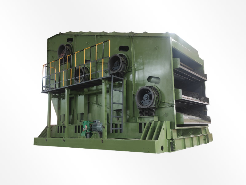
China has currently manufactured the ZGS series self-synchronous probability screening machines. This machine utilizes two vibrating motors rotating in opposite directions; the unbalanced force (inertial force) generated by the eccentric masses at both ends of the motors drives the screening unit to undergo reciprocating vibration in a specified direction. When the two vibrating motors rotate synchronously in opposite directions, the excitation forces produced by their eccentric masses cancel each other out in the direction parallel to the motor axes, while their resultant force in the direction perpendicular to the motor axes combines to form a single resultant force. As a result, the motion trajectory of the screening unit is a straight line. The relative surfaces of the two motor shafts are inclined at an angle in the vertical direction; under the combined action of this excitation force and the gravitational force of the material, the material is thrown upward, jumps, or moves forward in a straight line along the surface, thereby achieving the purpose of screening and grading the material.
Since the vibrating motor is directly fixed to the screen frame without any elastic connection in between, it forms a single-particle forced vibration system; as the screen machine operates outside the resonance range, it remains insensitive to load variations, ensuring smooth operation. The unbalanced forces generated add up or cancel each other out, causing the screen machine to undergo linear reciprocating motion, thereby defining its linear vibration trajectory. When materials are fed into the screen machine through the inlet and fall onto the first layer of the screen surface, large particles—whose size exceeds the aperture spacing of the first layer—are accelerated by the screen surface’s vibration, facilitating their separation; the remaining small-and medium-sized particles are then further separated by the second and third layers according to the same principle. The large particles on the first, second, and third screen layers simultaneously enter the coal crusher inlet for crushing, while the material passing through the third screen layer constitutes the qualified product, which is then directed to the next processing stage.
The probability screening system primarily consists of two main components: the vibration damping system and the screening unit.
(1) Shock Absorption System
The ZGS series self-synchronizing probability sieve features a suspended load-reducing system: the sieve body is hoisted onto a support frame using a rope clamp that connects a shock-absorbing spring, a cable helical buckle, and a steel wire rope; the spring serves to dampen vibrations.
(2) Sieving Unit
The screening unit consists of a screening box, a vibrating motor, and a screening surface.
III. Maintenance and Adjustment
(1) Lifting of the vibration damping system
Install the vibration damping system on the support frame as specified; suspend the screening machine using steel wire ropes and rope clamps; then adjust the adjustment screw to align the machine’s inlet horizontally and ensure that the four vibration damping springs are subjected to uniform force (this can be verified by measuring the compression height of each spring). If the compression heights are identical, the force distribution is uniform. A permissible tolerance may exist in the compression height of the springs on the front and rear vibration dampers; however, the compression heights of the two springs in each set must be adjusted to be identical. When a spring requires replacement due to damage, the entire set of springs must be replaced simultaneously.
(2) Pre-installation Instructions for Sieve Plate Installation
(1) Amplitude adjustment requirements and methods
When the machine is running under no-load conditions, set the screen’s vibration amplitude to 4–5 mm; alternatively, adjust the amplitude appropriately based on the coal quality (for example, use a higher amplitude – generally not exceeding 6 mm – when the coal is dense or the processing volume is high; use a lower amplitude when the coal is loose or the processing volume is low). This approach can extend the machine’s service life and reduce noise levels.
The method for adjusting the amplitude involves changing the eccentric coincidence angle between the two motors; however, the coincidence angles of the four sets of eccentric blocks on both motors must be made identical—otherwise, oscillation will occur. Once the eccentric blocks have been properly adjusted, a locking nut should be applied, and after the desired amplitude has been achieved, a locking washer should be installed and secured. The amplitude value can be directly read from the scale markings on the amplitude indicator plate; the number indicated by the horizontal coordinate of the intersection point of the two lines represents the adjusted amplitude value.
The article data is sourced from 360 Wenku.

Email:
honghekj88@163.com
 0086-0373-5579588

 Spare Parts
 EN